ARDUINO BASED INDUCTANCE METER
Dec 20, 2020

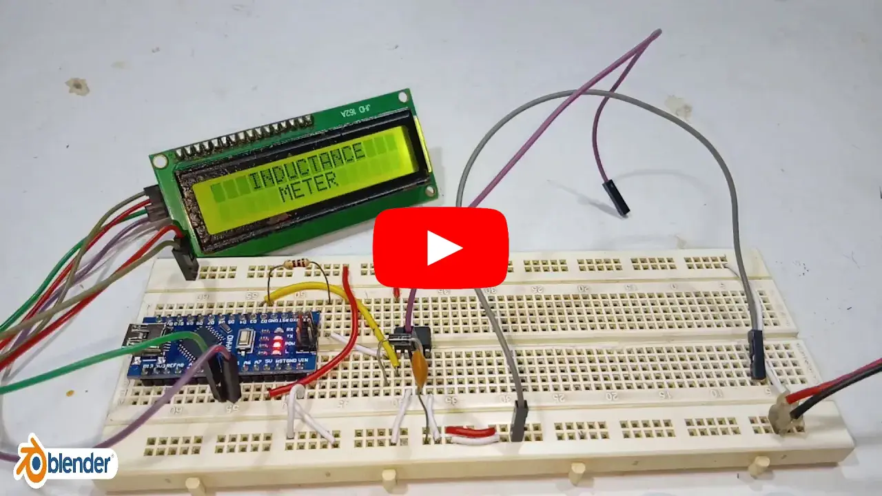
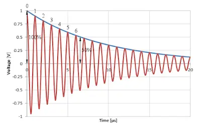
In the video i will show you how make a inductance meter using arduino. An inductor in parallel with a capacitor is called an LC circuit, this will oscillate when a supply is given and suddenly removed. it will oscillate in its resonant frequency. in ideal cases it will continue for ever. But in practical this circuit have some resistance so th out put waveform will be like this

After sometimes this oscillation will stop. For this we will continuously charge the capacitor in a uniform interval. Since all microcontroller have the ability to analyzing analog signals. The ATMEGA328 ADC is capable of sampling analog signals at 9600Hz or 0.1ms, which is fast but no where near what this project requires. So we will use a op-amp IC in comparator mode for converting analog signal to digital signal which i am using is LM358 As soon as the voltage on the LC circuit becomes positive, the LM358 will be floating (high)
So what we will do is applying a pulse signal to the LC circuit. In this case it will be 5V from the arduino. We charge the circuit for some time. Then we change the voltage from 5V directly to 0. That pulse will make the circuit to resonate creating a cushioned sinusoidal signal oscillating at the resonant frequency. What we need to do is to measure that frequency and later using the formulas obtain the inductance value. We will use the arduino to measure the frequency and calculate the value. The resonant frequency is related with the next equation:
\[ Fr = \frac{1}{2\pi \sqrt{LC}} \]
So we could obtain the L value because we know the resonant frequency (Fr) that we've just measured and we also know the values of pie and capacitor (C) because it's a component that we've selected. All we need is to obtain L from this equation. we will find the vale of L from the next equation
\[ L = \frac{1}{(2\pi Fr)^2 C} \]
Components Required
- 1 x Arduino NANO
- 1 x LM358 Low Power Amplifier
- 1 x LCD Display
- 1 x 1KΩ
- 2 x 1N4007
- 2 x 1µF Capacitor
- 1 x I2C Module (Optional for easier LCD wiring)
- Connecting Wires
Normal LCD Connections
| ARDUINO PINS | LCD DISPLAY PINS |
|---|---|
| GND | VSS |
| +5V | VDD |
| Center of Pot | VO |
| D2 | RS |
| GND | RW |
| D3 | E |
| NC | D0 |
| NC | D1 |
| NC | D2 |
| NC | D3 |
| D4 | D4 |
| D5 | D5 |
| D6 | D6 |
| D7 | D7 |
| +5V via Resistor | A |
| GND | K |
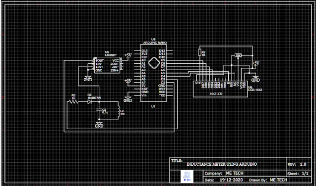
Circuit Diagram

I²C LCD Connections
| ARDUINO PINS | I²C LCD MODULE PINS |
|---|---|
| D4 | SCL |
| D5 | SDA |
| +5V | VCC |
| GND | GND |
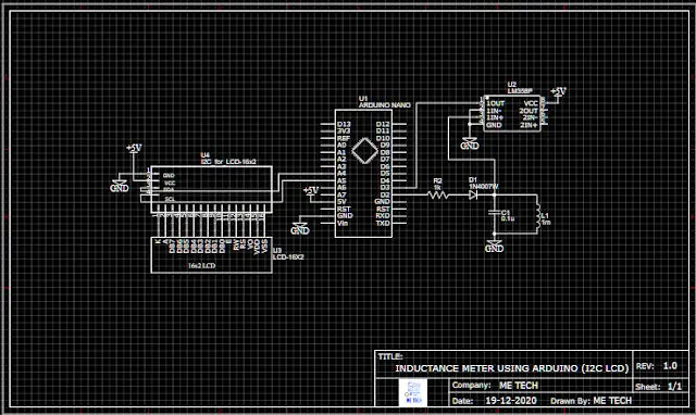
Circuit Diagram

Code for this can be found by clicking here
If you like this video hit the SUBSCRIBE button and give a LIKE.